
Which effective powers can be expected around broadcast towers?
by Peer-Axel Kroeske, DL2LBP
The ERP of broadcast transmitters only gives an initial indication of how strong the signal arrives at the receiver. In theory, a 100 kW transmitter should arrive 20 dB stronger than a 1 kW transmitter from the same location. But as soon as different antennas are used, radiation patterns will show different results. In many cases, the coordinated power patterns reflect this poorly.
Reasons for losses are: bad resonance (SWR), cables and connectors. Professional cable feeds attenuate the power by 0.6 dB per 100 Meter on 100 MHz. 3 dB loss in total are common. I will refer to transmission power as what is actually emitted by the antenna.
No single broadcast transmitter distributes the transmission power completely evenly in space like an isotopic radiator. In the broadcast business this is not intended anyway. The optimum would be a diagram in the form of a disc that is as flat as possible.
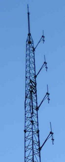
Simple vertical radiators (groundplane antenna or vertical dipole) distribute the power like a donut. In extension of the rod, radiation is minimized. The "donut" has a gain of 2.15 dB compared to the isotope radiator. This is the reference for ERP. However, installation on the side of a mast has a considerable influence on the diagram. Experience shows that signals on the back of the mast can be attenuated by up to 20 dB, while on the side of the antenna installation they can even be amplified by up to 3 dB. Only a vertical antenna at the top of the mast has an approximately omnidirectional character.
A horizontal dipole also radiates the transmitting power in ERP upwards and downwards, but in two main directions.
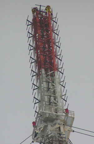
If a second or third vertical antenna are installed on the other sides of the mast, radiation gets more uniform again. However, multiple radiation points create interference patterns. This can be optimized again by installing directional antennas on all four mast sides. Overlaps of the power pattern coils should be avoided. Complex directional patterns can be realised by distributing the power to the individual sides and by phase shifting. However, the coordinated 10° step directional diagrams are only roughly approximated.
This concept has two further advantages: The directional antennas provide an additional gain in the plane of 3 to 6 dB. Rule of thumb: x antenna elements give the x-fold power, with the dipole as the first element, the reflector the second and all directors following.
With horizontal polarisation, omnidirectional radiation is only possible if antennas are installed in at least three directions.
Stacked antennas produce further gain in the plane. The rule of thumb is similar: x-fold power with x levels of stacking. This may cause additional loss in the distribution components, but they are offset by the additional gain.
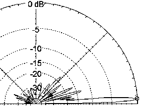
Investments in complex antenna systems lower electricity costs and after all it is worthwhile to have a good signal in all directions. If you ever have monitored broadcast signals during a flight you may have noticed that signals in 100 to 200 km distance come in stronger than directly below. With four stocked antennas, the vertical opening angle is reduced to 10°, with 10 to 30 dB reduction outside the coil. Strong transmitter coils only reach 3° elevation.
This is relevant for Sporadic E propagation. At short distances of 1000 km, the signal is reflected at about 90 km height, resulting in 17° elevation. Powerful stations with stocked antennas will produce a significantly reduced ERP, while they dominate distances over 2000 km where the reflection height is 150 km above ground.
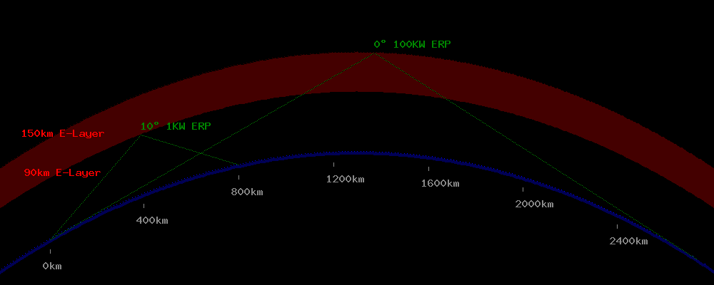
An antenna at 300 meters above ground with 100 kW ERPmax in a flat environment will have a significantly reduced ERP of only about 100 watts to 10 KW in the near field (>3° angle) of about 5 km around the mast on the ground - strongly fluctuating because the sidecoils have hardly predictable patterns.
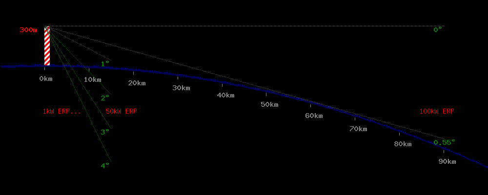
The table shows an example with the reference signal strength of 128 dBµV by a transmitter with 100 kW ERPmax in 1km distance in free space in the main beam direction. In the distance, ground attenuation increases caused by the low elevation of the signal path. In this case the stacked trasmitter antenna with an opening of +/- 3° is mounted 300m above ground. Up to 20 km distance the signal level is almost constant. However, in a real environment you must add signal losses by trees, buildings and topography, increasing with the distance.
| Distance | 100m | 500m | 1km | 4km | 8km | 16km |
|---|---|---|---|---|---|---|
| Distance loss dB | -20 | -6 | 0 | 6 | 9 | 12 |
| Ground attenuation dB | 1 | 5 | 8 | 9 | 10 | 11 |
| ERP loss by vertical deviation | 20-40 | 20-40 | 20-40 | 10 | 3 | 1 |
| Signal dBµV | 107-127 | 89-109 | 80-100 | 103 | 106 | 104 |
On a small Danish transmitter coordinated with 160 watts ERP, I could observe that the power amplifier produces 280 watts. Cable length was only 30 meters. So perhaps 140 watts arrive at the 4 stacked vertical antennas. The stocking increases the effective power to 560 watts ERP. Mast reflections can increase this up to 1 KW ERP in single directions. On the shaded side, however, the signal is reduced up to 20 dB to 5 watts ERP. Even if omnidirectional radiation is coordinated, many smaller transmitter operators do not invest in additional antennas. They would rather increase power if controls and enforcement are not too strict.
At a larger German site, 25 KW of omnidirectional radiation is coordinated for several programs. The power amplifiers produce 3.5 KW. Thick cables run up the tower, so I assume that 3 kW reach the transmitting antenna. In four directions there are 16 horizontally stacked dipoles each, behind them grid reflectors. Each dipole group is fed with 750 watts. The reflectors double the ERP. 32 fold power would be 24 KW ERP.